Background
If you’ve talked to me in the past two years, you probably know I’ve become obsessed with building, collecting, and sometimes actually using split ergonomic keyboards. Over this time I’ve had to learn a lot about computing on both the hardware and software sides in order to get over various hurdles when building and using the keyboards. It scratches my itch to have something physical to represent what is a very digital interest of mine (software).
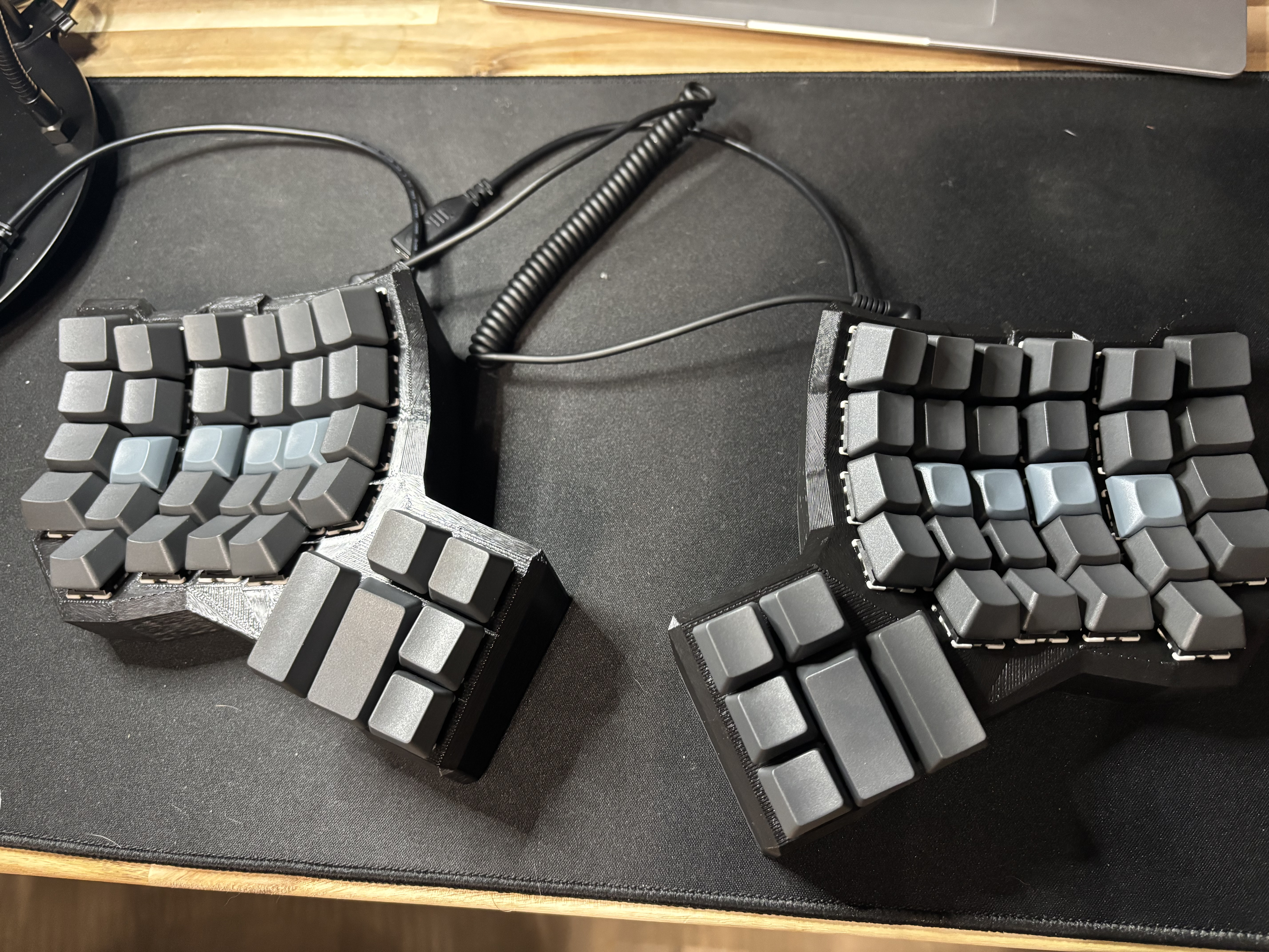
At the time of writing I own keyboards ranging from 36 keys to 68 keys (the Dactyl CC I’m writing about today!). I’ve tried many sizes in between, with various layouts that have different ways of handling modifiers, such as home row mods, bottom row mods, and thumb key tap-hold setups.
When I first started this change 2 years ago, I also chose to switch my layout from QWERTY to Colemak Mod-DH, which has presented its own hurdles and benefits – something I could probably write an entire post about. Looking back, I wouldn’t have made the switch — the downsides have outweighed the benefits for me. I’m now in an interesting situation where I do not want to spend the time to re-learn QWERTY on the split (I can type just fine on standard keyboards and laptops) even though many keyboard shortcuts are now incredibly awkward, which is my main gripe with the change.
I also switched to using Neovim as my primary editor around the same time and have stuck with it. I think it’s obvious to readers by now that I have a possibly unhealthy desire to make my workflow very keyboard-driven :). It’s a wonder that I stuck with all of this without losing motivation, because the first few months were ROUGH. Typing at ~30 wpm or less, awkwardly undoing actions I didn’t mean to do in nvim, and trying to figure out how to do what I wanted. It’s a wonder I was even mildly productive.
What you’re here for, the build
This keyboard represents my current “endgame” after 2 years of finding what I prefer in my keyboards and workflow. I have found that I like to have many keys available on my base layer, something that feels unpopular – if one were to browse reddit.com/r/ergomechkeyboards, for example. Before this, my favorite was a factory-refurbished Kinesis Advantage 2 I picked up early last year. The sculpted keywells and thumb key layout really grew on me and was the least awkward for many keyboard shortcuts basically out of the box. There are some shortcomings about it that made me want to build something more custom though:
- Lack of advanced programming features.
- I really like being able to program TAP-HOLD functions on many of my thumb keys on my other custom keyboards running QMK, but Kinesis’s Smart Set software does not have this feature, reducing all my keys to a single function.
- Cherry brown switches
- These switches aren’t horrible but they are not my preferred choice of switch, nor does Kinesis offer any switches I really like from the factory.
- Sound
- This is last because it isn’t super important to me, but it is still a negative. The large hollow case (even with some microfiber cloths I’ve stuffed inside) gives a very hollow sound when typing that I don’t really like.
With these minor grievances in mind, and a newish 3d printer that I bought last year, it seemed like a fun project to explore building a hand-wired Dactyl CC to fill those gaps I saw in the Kinesis… and off we go.
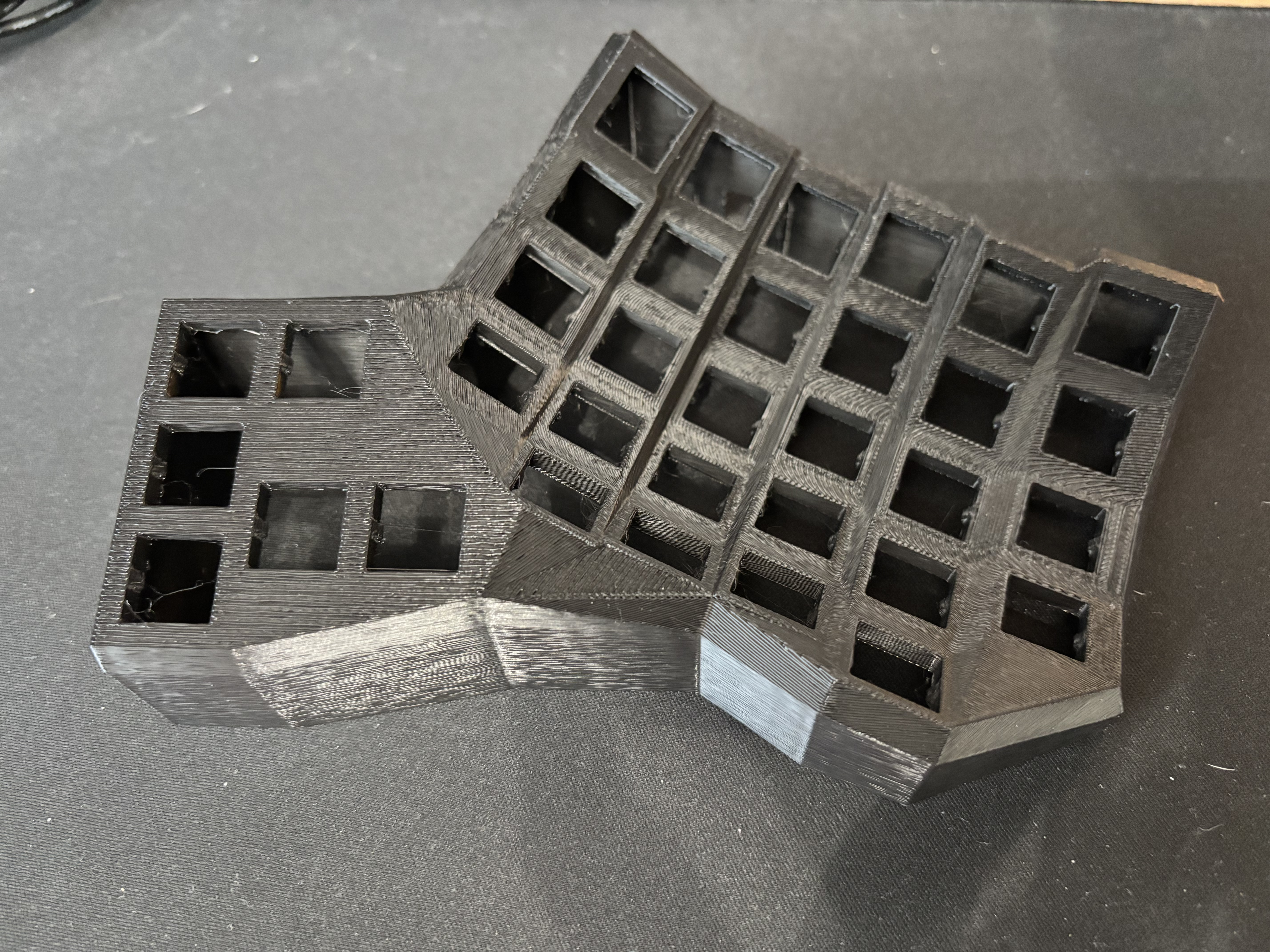
The print
I generated the STLs from the build script in the original repo https://github.com/mjohns/dactyl-cc and fed them into OctoPrint. I chose to go with a simple 0.2mm layer height, 20% infill, and default tree supports. The print came out clean — supports were easy to remove, and the case was sturdy enough for switch installation.
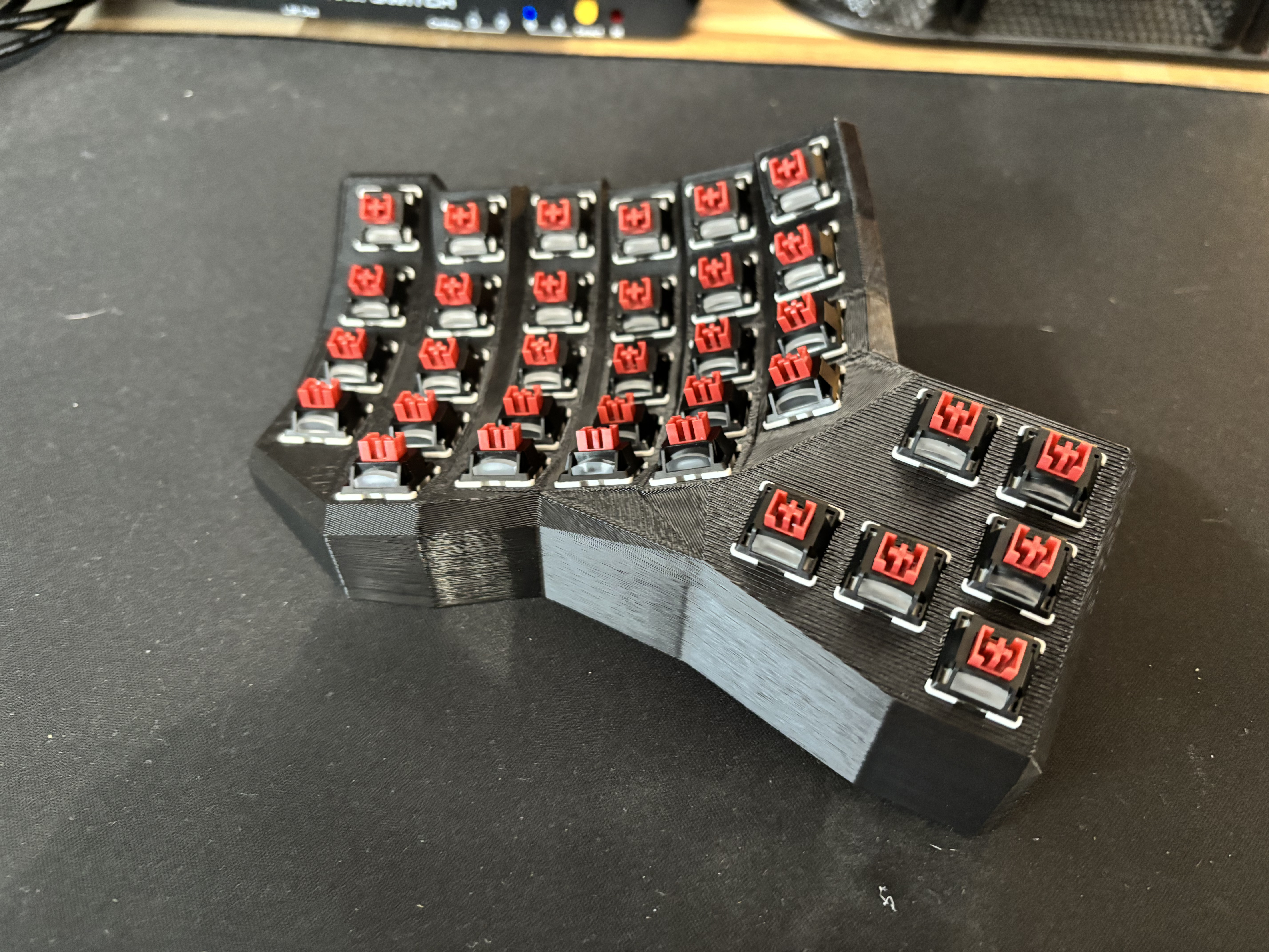
Starting assembly
So the first step was to simply insert my switches (Akko Draculas) into the cases, this went without a hitch.
Next, I wired the matrix. I used copper tape to run most of my columns, with some solder at each joint with the switch to ensure good connections. In places where columns needed sharp turns or odd routes, like connecting to the thumb keys, I initially ran copper tape, but on the second half I found it much easier to simply cut some pieces of wire and solder those.
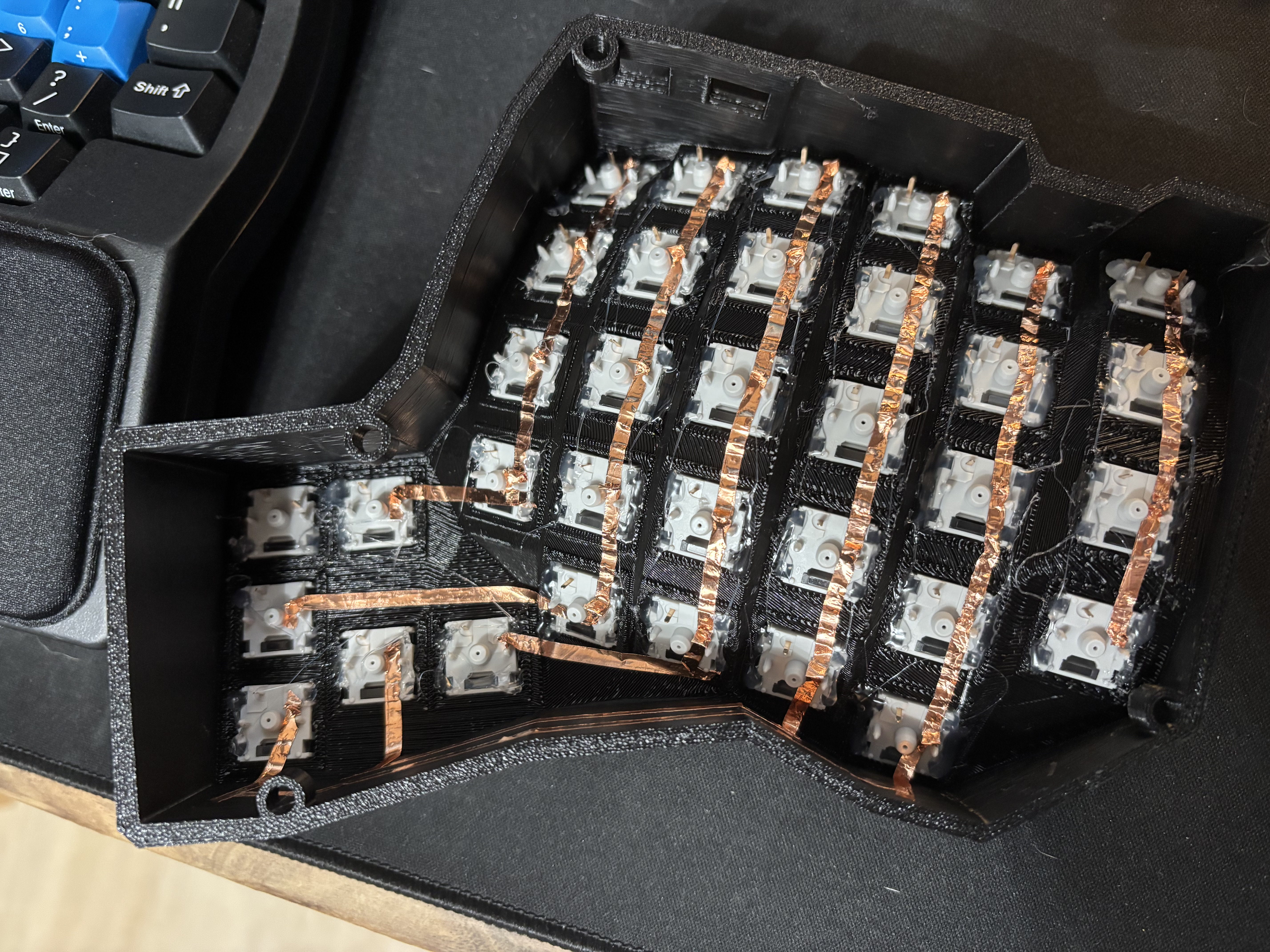
After the copper tape is in place, I then hotglued my switches to the case. The reason for doing this after the copper tape is because the hot glue would create a very irregular, bumpy surface for the tape to run across, increasing the chance of loose connections. By doing it after, it also aids in holding the tape in place and helps insulate it from other wires in the assembly.
Next, I ran my diodes for the rows, this went rather well without much issue. Orientation is very important, and somehow I managed to get all the diodes right on the first try.
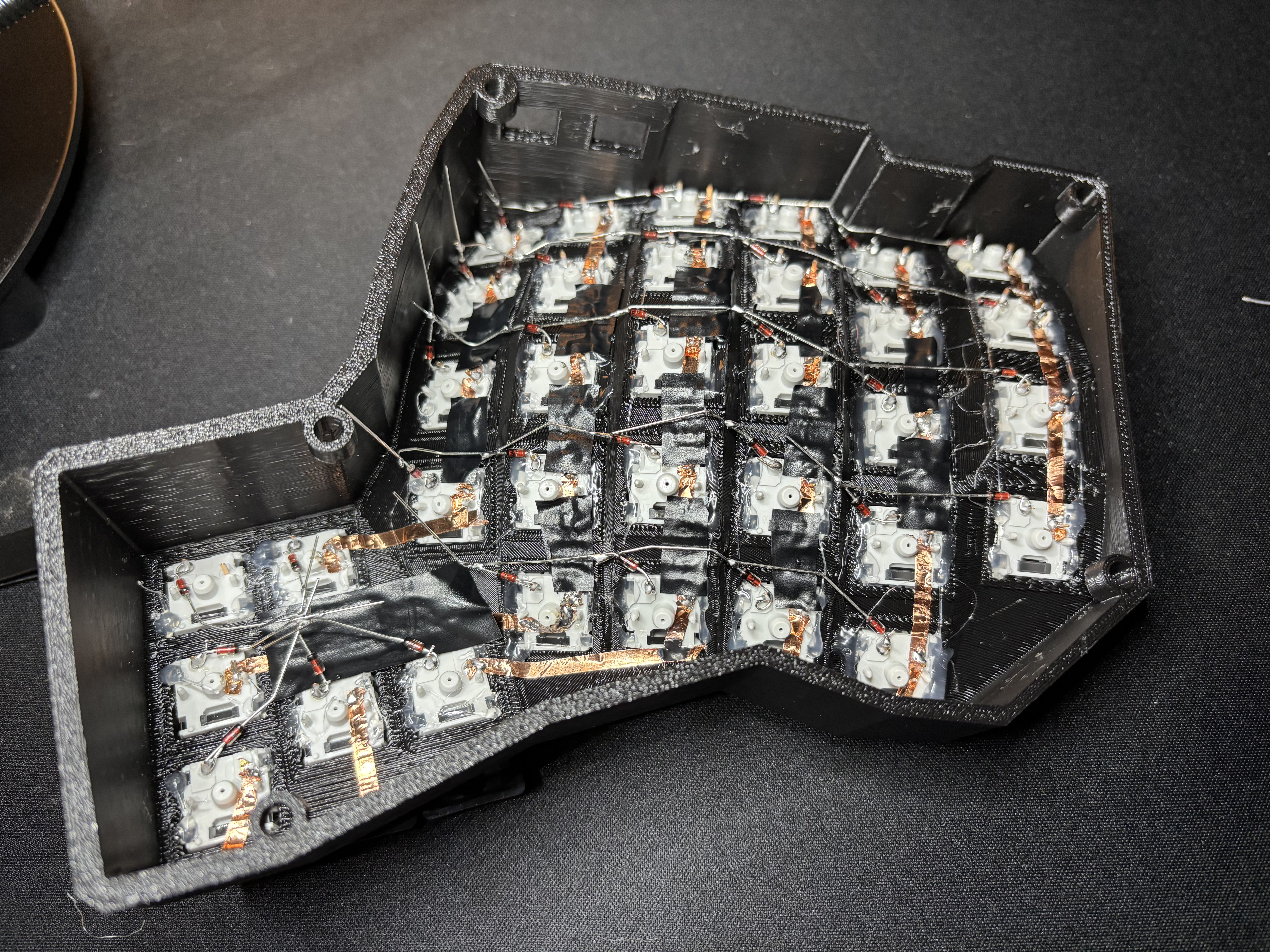
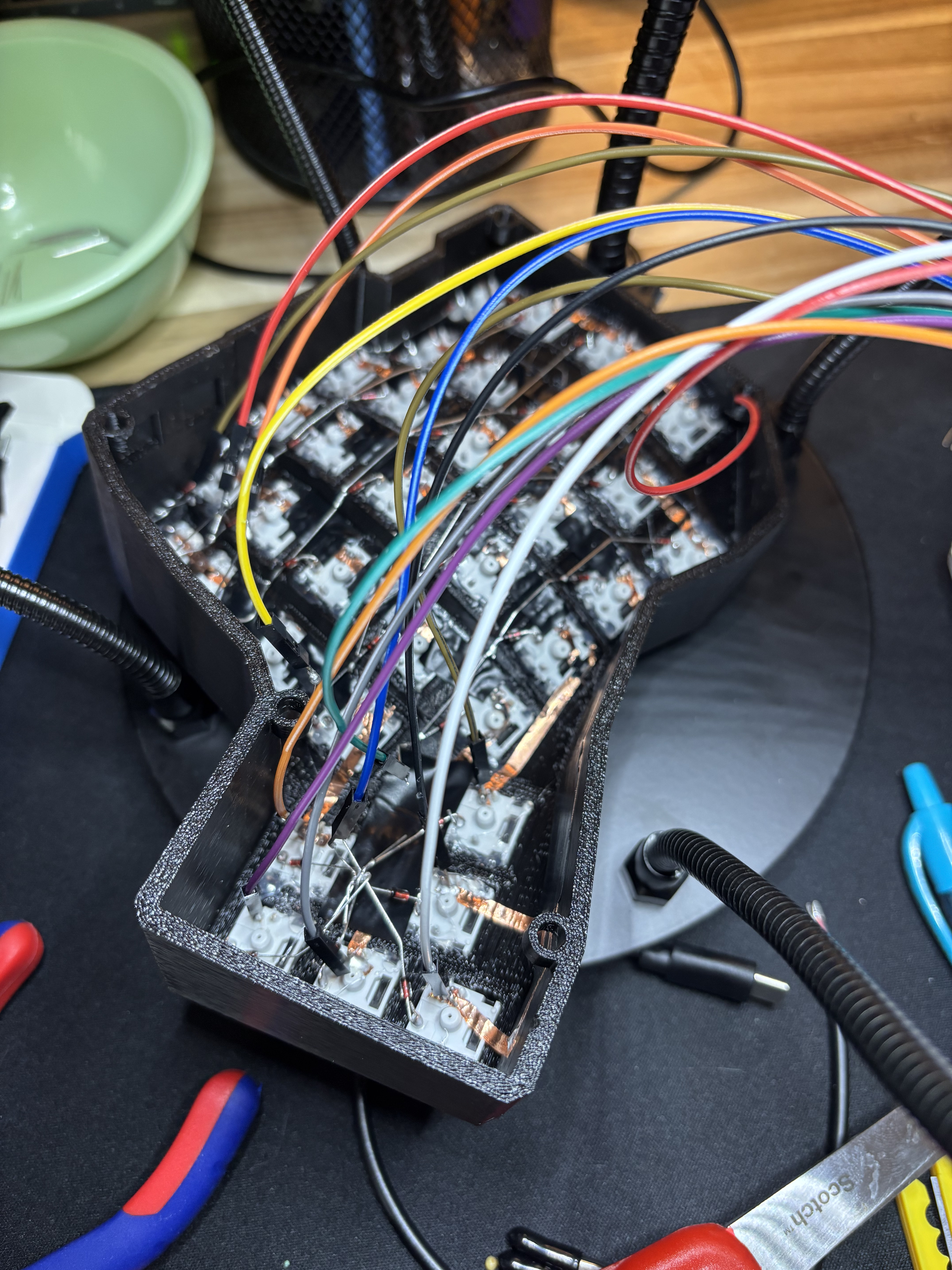
After this, I simply added some female-terminated dupont connectors to the end of each column and row, which I could easily connect and disconnect from my microcontroller to test and develop the software configuration before soldering anything.
Now, I think it’s very important to mention that I did not do much research about the “correct” matrix for this keyboard, so my wiring was simply what makes the most sense to me at the time. This is very important later, because it resulted in me having to do much more work on the software side to define my own matrix and entire keyboard in QMK.
Programming the microcontroller
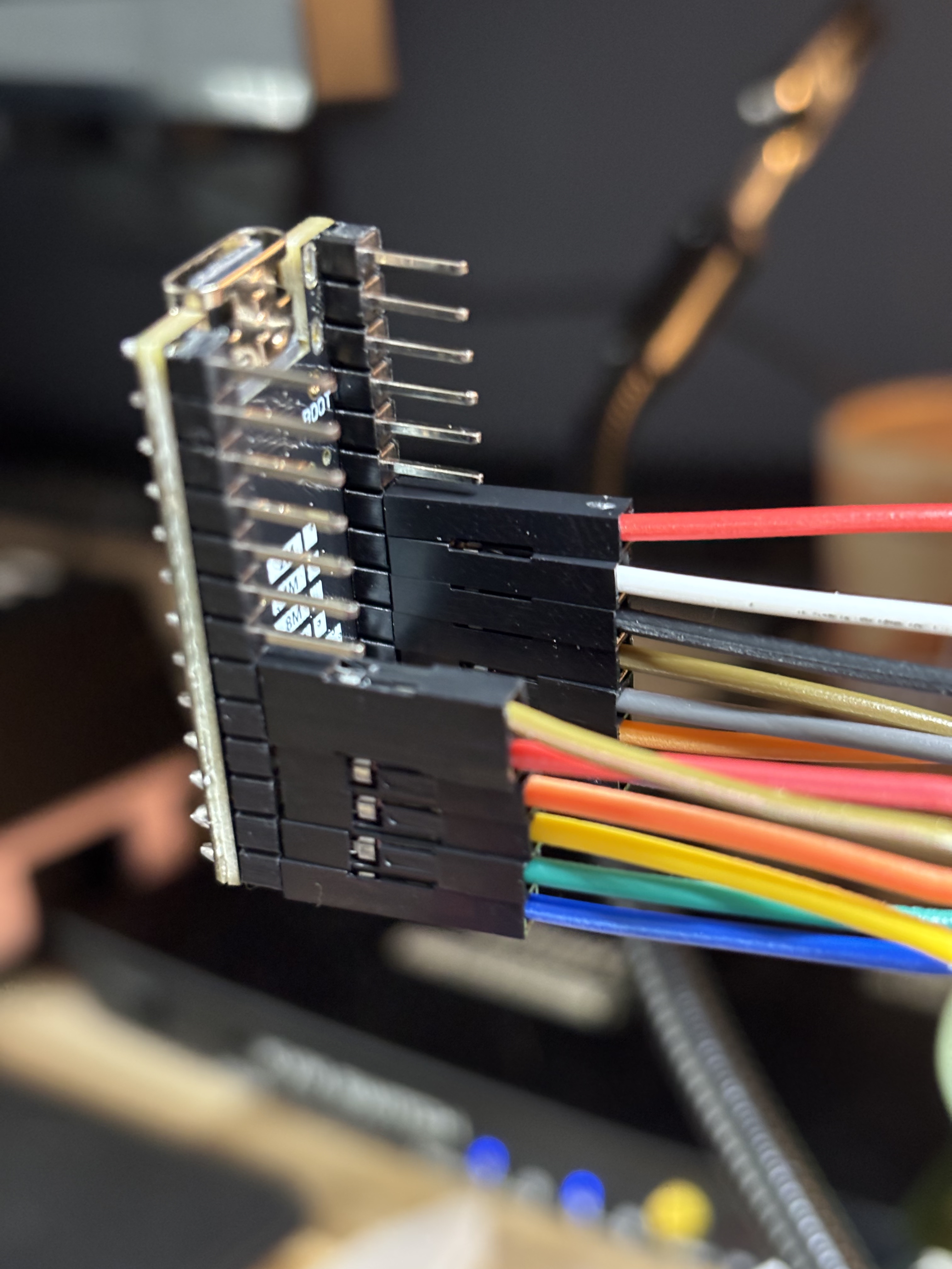
The microcontroller that I chose to use is a “pro-micro” RP2040. My experience and understanding here is limited, but from what I gather, the “pro-micro” portion is a certain physical size and pinout, but RP2040 is a much newer chip which has great specs for cheap. Due to this choice though, I again created another condition where I deviated from the documented path and had to learn a bit more to get things working.
I started by connecting all my columns to pins on one side and, rows to pins on
the other and dove into QMK documentation about setting up a keyboard.json
file for my build, starting with the original Dactyll CC one as a baseline. I
simplified it to only include one half and chose to worry about the split logic
later, something I think was a good choice and recommend. Along with this, I
also set up a simple keymap.c file for the single half as well.
Using this, I iterated on my configuration until I had half a keyboard functioning as I expected. I faced a few hurdles, mostly due to trying to take shortcuts without reading and understanding documentation fully. Some hurdles:
- Choosing a development board – Initially, I wasn’t sure which RP2040 board QMK supported. I got lucky that setting it to ‘promicro_2040’ got some keys working.
- Incorrect pin names in my
keyboard.json– here I wasn’t aware of the ability to use both “pro-micro” names for the pins as well as the documented names on my chip. I started with pro-micro because that was in the dactyl cc config, but I was only using some of the same pins, so I only had partial functionality. After digging into the documentation, and finding some blogs online about the chips I had, or similar chips, I found the right pins. - Incorrect matrix – I think everyone who has made a QMK-based keyboard has encountered this while developing it. The order of various parts is very important, and it can be easy to mess up, at least for me.
The next thing is to figure out how to make the keyboard halves talk to each other. One doesn’t want to plug in each half of their keyboard to a dedicated usb port after all (would various shortcuts and modifier combos work that way?). I chose to use a rather common option in the community which is connecting the halves with a TRRS cable, and using QMK to do much of the legwork for me. It took a bit of trial and error, but I eventually got it working (I have to mention that my matrix and keymap both had to be adjusted for this to include the full keymap with both halves!).
With this, I was now ready to document all of my connections, because remember they are temporary connections while I find which pins to use. So I took out pretty much all my wires connected to the rows and columns here, cut some new ones that are varying lengths to help it all fit inside the closed case at the end, and solder the new ones to the keyboard and the microcontroller this time. I also needed to hot glue my TRRS and USB connectors into place in the case.
I needed to add the female threads for the bottom case screws into the already-present holes for them. This was as simple as setting them in the location, and using a soldering iron to warm them just enough to melt the surrounding filament and hold them in the case.
I then attached the bottom plate to the keyboard, barbarically stuffing the microcontroller and cables wherever they fit inside.
I installed my keycaps (a blank PBT set for the Kinesis Advantage 360), and I now have another functioning keyboard!
Closing thoughts
Despite planning for this to be my ‘endgame’ build, I couldn’t resist experimenting. Generally, I prefer tactile switches, and I’ve tried enough that I really should just trust my gut. Still, I chose to use linear switches on this one, and I do think that was a minor mistake. It feels and types great, and this hasn’t stopped me from using it for the past month, and I expect many more, but I just have many more errors with linears for whatever reason, and don’t like the experience as much.
Other than that single gripe, I’m ecstatic about how this project went. I learned so much more than I thought I would, considering I’d built a half dozen or so keyboards before this. Everything else was based on kits or used PCBs, and always had the matrix -> pins, and ultimately the entire QMK side of things sorted for me. I would just adapt the keymap to my likings and enjoy the keyboard. This Dactyl CC feels much more like my work in a way previous builds never did (I do not mean to discredit github user mjohns, who actually created the original dactyl cc! Thank you for your work!)
Oh, and the best part? I’m pretty sure that it wasn’t even 24 hours after completing this one that I was starting prints for the next keyboard… I have a problem, don’t I?